Thermal Analysis of PowerEsim Help Manuals |
|
| PowerEsim is a free web-based software providing power supply (SMPS) design, transformer design, magnetic design, loss analysis, thermal analysis, waveform analysis, MTBF analysis, BOM building, DVT analysis and optimization of power supply (SMPS). | |
| Click to try PowerEsim (www.powerEsim.com) | |
9
Thermal Analysis
9.1
What is thermal analysis?
Thermal analysis is a tool to let user to place component, PCB, heatsink, etc. and enter the losses of each component. With just a click and wait for a few second the thermal result will be displayed. User can treat it as a standalone tool to estimate the thermal behaviors of any product. If a power supply has initialized, all the component with its corresponding losses of the power supply will be automatically transfer and synchronous to the thermal analysis tool.
The thermal simulator considers the conduction effect, convection effect as well as radiation effect.
9.2
How to start the Thermal Analysis?
Click on the ![]() at the left main menu to start Thermal
Analysis
at the left main menu to start Thermal
Analysis
9.3
Interface Requirement(s) for viewing Thermal Analysis?

This Thermal Analysis Interface is developed using the Macromedia
Flash MX 2004 and JavaScript
2.X. In order to view the plots, Flash Player 7.0 or above should be installed
in your computer. The suggested web-browser is Internet Explorer 6 or above
on the Windows platform.
9.4
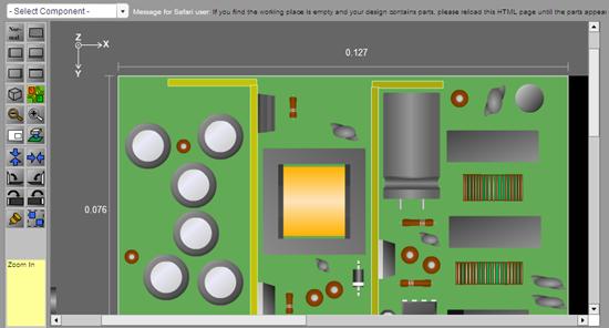
It is a 2D and 3D Thermal Analyzer
![]()
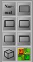
There are 8 views at Thermal
Analyzer.


At the left top corner, you will
see the following sign to indicate the type of current view.
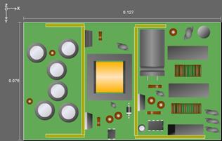
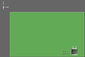
Figure:
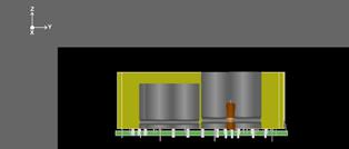
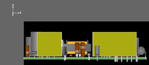
Figure: Left view Figure: Front view
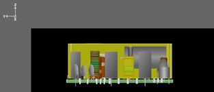
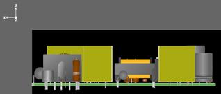
Figure: Right view Figure: Back view
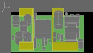
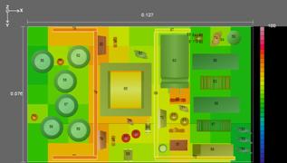
Figure: 3D view Figure: Thermal view
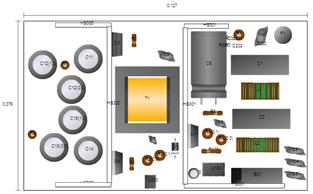
Figure:
Print view
9.5
Place a part
Use the mouse the drag the component into the working area.
9.6
How to find a part by designator?
![]()
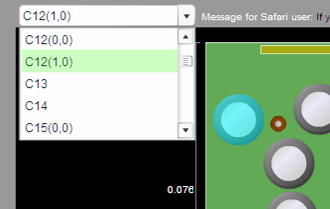
Select the part designator from
the selection box. The part will be highlighted with cyan overlay.
9.7
How to add a part for thermal simulation?
You can add parts for thermal
simulation. Click on ![]() and add a part from database or create a part
of your own. You can also add a part by
and add a part from database or create a part
of your own. You can also add a part by ![]() at the top of Thermal Analysis page.
at the top of Thermal Analysis page.
If the added part is selected
from database, all the thermal parameter has been already model, user are only
needed to enter the power losses.
To add part from database, select
component type at the combo box below. Click “Add”. The component page pops up.
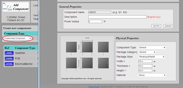
To customize the part, select “Customized
Component” at the combo box “Component
Type” or Click “Add”. The generic
component page is popped up. You can input the shape and dimension of the part.
The size and shape will be previewed at the left hand side. The material of the
part is also needed.
![]()
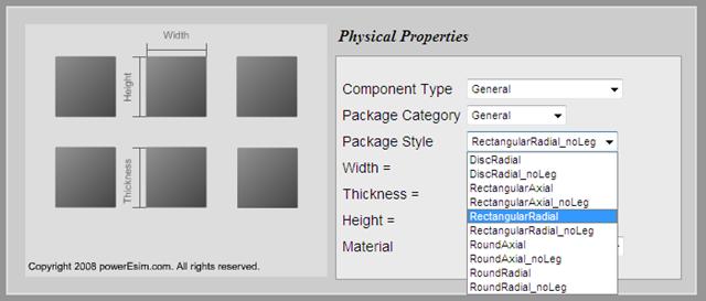
A lot of predefined package have
been build to facility user. User can select the package style of the part from
“Package style” combo box. The size and shape
will be previewed at the left hand side. This shape will be as same as in
Thermal Analyzer. No hand drawing is needed.
9.8
Printed Circuit Board PCB and heat sink can also be added
After initializing the power
supply design, there are a PCB and a Heat sink. The
first PCB added to the design is defined as the main PCB. It cannot be moved by
dragging.
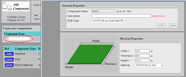
To add the PCB, select “PCB”
at the component type combo box and click “Add”. You can customize the size and
the material of the PCB.
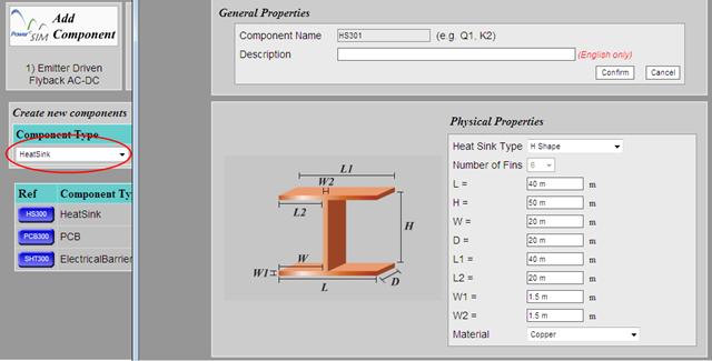
To add the heat sink, select “HeatSink” from the Component Type and click “Add”. You can customize the shape,
dimension and material of the heat sink.

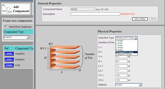
User can select the basic form of
the heat sink from “Heat Sink Type”
![]()
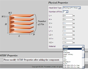
User can change the material of
the heat sink from “Material”
9.9
Defining Highlighted Losses of added parts
For any
added parts, you can set their power losses. Heat sink and PCB are not allowed
to set power losses.
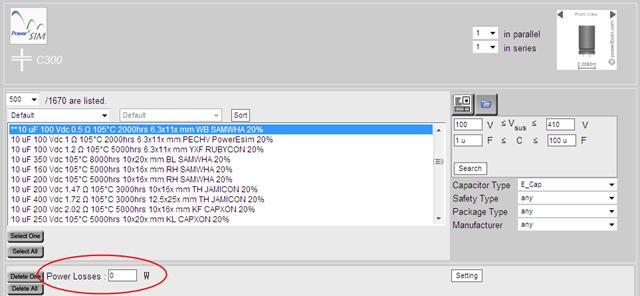
If the
added part is selected from database, the component selection user interface
will provide a text box “Selected Losses” for user to enter the losses of
that component
![]()
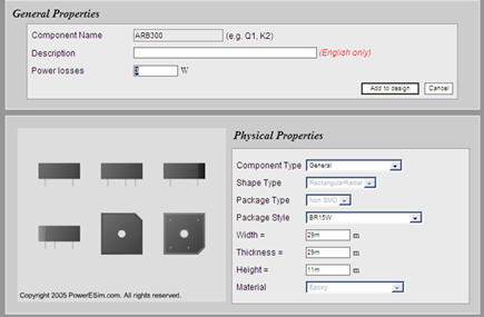
If the
added part is customized, user has to enter the losses of that component at the
“General Properties” page.
9.10
Start thermal simulation
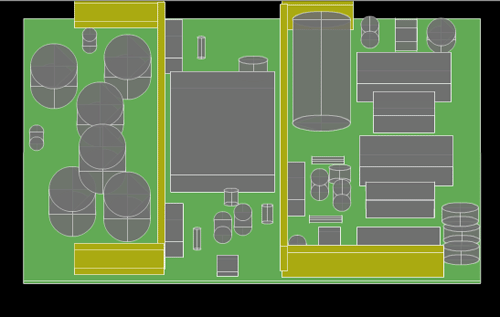
After placement of components on the working area, you can start the
thermal simulation by triggering with the button![]() shown. After a few seconds (duration depends on number of components and
the size of PCB and heat sinks), the color of the component is changed
according to the temperature.
shown. After a few seconds (duration depends on number of components and
the size of PCB and heat sinks), the color of the component is changed
according to the temperature.
9.11
 Color map for temperature distribution
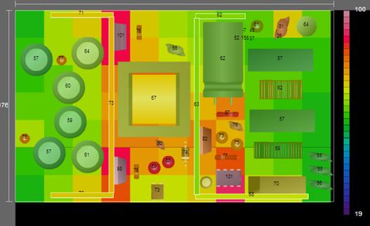
![]()
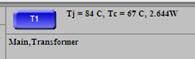
There is a color bar on the right hand side of the main PCB. Place
the mouse pointer over the bar. The defined temperature value is shown. To get
the temperature of each component, click on it and its Junction and Case
temperatures appear at the bottom of the working area.
9.12
How to get and update the physical location of parts after placement?
The physical location of particular
part is indicated at the left bottom. You can type in the location of the
selected component and click “Update” to set the location.

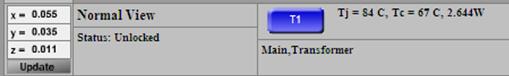
Figure: component
location
9.13
How to view or edit a part at Thermal Analyzer?
![]()
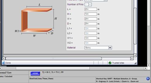
Figure: Link to component page
Select a component on the Thermal
Analyzer. The designator will be appeared on the blue button on the interface.
Click and view the part in component page.
9.14
Different thermal results at different combinations of Vin
and Iout
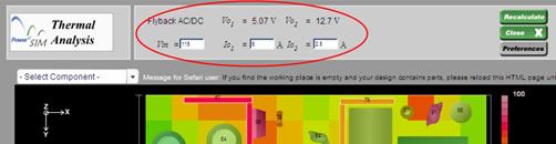
At the top bar, you can change
the Vin and Io of the power supply. Click on “Recalculate” to update the changes.
9.15
How to turn the board to 3D view?
![]()
After triggering the 3D view, the position of the components is
locked. You can drag the working place to upward and downward to turn the
board.
9.16
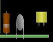
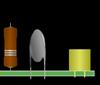
Create different package style of components
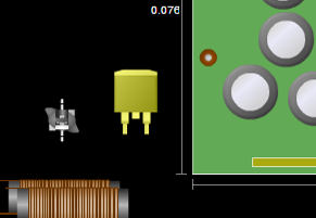
The shape of component appears at the Thermal Analysis. Interface is defined by following criteria:
- The package style of the component (e.g. TO220). We have prepared about 200 common package styles in the database.
- If the component does not have package style provided or its package style is not in our database, its shape is defined by its component type (e.g. Resistor or Diode), the shape (e.g. Rectangular or Circular) and the soldering features (e.g. SMD or non-SMD).
- Transformer has shape defined by its core (e.g. EE, ETD or Toriod) and solder method (e.g. Vertical or Horizontal).
- If the component is a heat sink, its shape is defined by the number of fins, the length of fins and the fin types (e.g. rectangular or triangular).
- If the component is a PCB, its shape must be a board like and the thickness of PCB is set at the Edit component interface.
- Otherwise, the component will be shaped as a simple block (e.g. Rectangle or Cylinder)
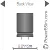
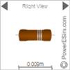
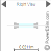
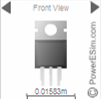
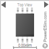
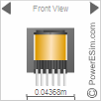
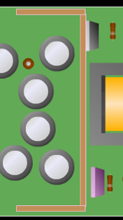
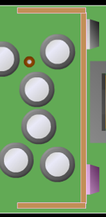
Figure: The shape of the components (Capacitor, Resistor, Fuse, TO220, IC and Transformer)
9.17
How to zoom in or zoom out the working area?
![]()
Figure: The
buttons to zoom out (left) and
zoom in (right)
Click the zoom
in or zoom out button.
9.18
Select multiple components and move them together
Press and hold the SHIFT key, use mouse to select multiple
components. Then, release the SHIFT key and drag on one of the selected
component. The selected components can be moved together.
9.19
Group and ungroup components
![]()
Figure: The
button to group components
After the multiple selection of component, click on group button. To
ungroup, click on the grouped components and click on the group button again
9.20
Lock a component in position
![]()
Figure: The
button to lock components
Select a component or a group by clicking it and then click on the
Lock button
9.21
Attach two components by the shortest distance
![]()
Figure: The
button to attach components
![]()
Move 2 components within 100 pixel distance. Select them together by “SHIFT” key and then click![]() . The component are attached together horizontally and
grouped. This feature is very useful to attach power devices to heat sink. If you click
. The component are attached together horizontally and
grouped. This feature is very useful to attach power devices to heat sink. If you click![]() , the
components are attached vertically.
, the
components are attached vertically.
9.22
How to ungroup the attached components?
![]()
Figure: The
buttons to split the attached components
Select the
2 attached components together by holding “Shift” button, and click on the
Group/Ungroup button.
9.23
How to Rotate Components?

Figure: The
buttons to rotate components

![]()

![]()
There are 4 ways to rotate the components.
- Select a component or a group to rotate it clockwise at Top view.
- Select a component or a group to rotate it anti-clockwise at Top view.
- Select a component or a group to rotate it clockwise at Front view.
- Select a component or a group to rotate it anti-clockwise at Front view.
9.24
Details of short-cut keys which help a lot
These are the short-cut keys provided by the interface:
- K - Toggle lock to the selected component or group
- SHIFT - Multiple selection
- G - Group components together
- N - Ungroup components
- Left arrow - Move selected component left by one pixel
- Right arrow - Move selected component right by one pixel
- Up arrow - Move selected component up by one pixel
- Down arrow - Move selected component down by one pixel
- "+" - Zoom in
- "-" - Zoom out
9.25 Put SMT component on the PCB
![]()
Figure: The
button to the to put SMT component to PCB
You can attach the component on
the PCB
![]()
 Prev.: Loop Analysis Prev.: Loop Analysis | Next: MTBF Analysis  |
Click to try PowerEsim (www.powerEsim.com)
|
Home | Download | Useful Link | Video Demo | About | Contact Us | Disclaimer | FAQ | Statistics Account Management | Options | Preferences | Help |
