Magnetic Builder (Magnetic Design Software, Inductor and Transformer design tool) |
|
| PowerEsim is a free web-based software providing power supply (SMPS) design, transformer design, magnetic design, loss analysis, thermal analysis, waveform analysis, MTBF analysis, BOM building, DVT analysis and optimization of power supply (SMPS). | |
| Click to try PowerEsim (www.powerEsim.com) | |
Magnetic Builder is a useful magnetic design software. It is a tool for user to create his/her own magnetic component (inductor and transformer) by selecting different ferrite core, bobbin type and winding method. Engineering drawing will be automatically produced to reduce user work load.
All the transformer and inductor built can be saved and reused onto a power supply, as long as the winding number are matched.
Inductor/Transfomer are necessary parts of switching power supply circuits.
The Advantages of Using Transformers
Transformers used with the three basic topologies offer certain advantages over the simple circuits introduced in the previous section. Namely:
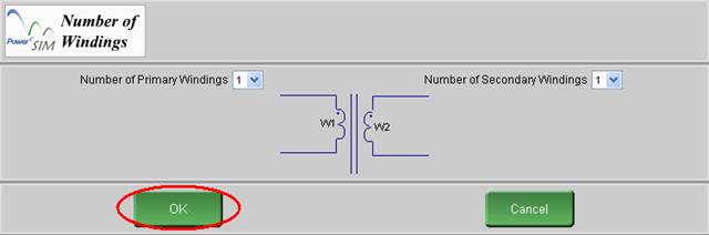
Click “Magnetic Builder” a “Number of Windings” page appear for user to first defining the number of primary winding and number of secondary winding.
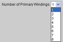
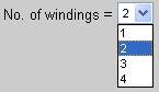
The number of primary winding and number of secondary winding can be change. The default value is one.
![]()
Click the button “Flux Band”
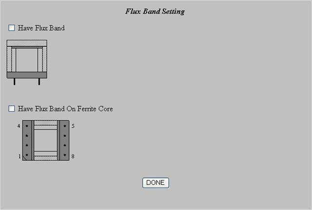
Two type of flux band are supported. Click the checkbox to add the flux band.
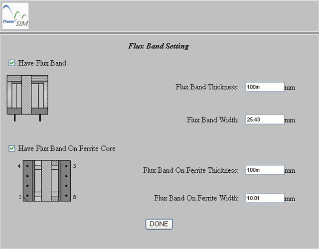
After clicked the checkbox, the core with the flux band can be preview. The Flux band thickness and width can be set.
![]()
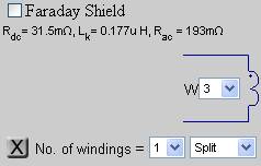
Extra Winding can be added by clicking “Add Pri Wdg” or “Add Sec Wdg.” The usage of this feature is recommended for non-operating winding only. User is recommended to preset the proper winding number at the “Number of Windings” page.
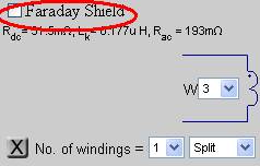
The user can change a particular winding to Faraday Shield. Only extra windings can be changed to Faraday Shield.
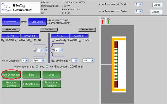
After creating a new transformer/inductor, you can add it to the design by pressing “Add Component”.
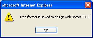
When the transformer/inductor is added, the message with transformer's designator is shown.
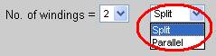
User can “Split” a winding to several section by choosing from “No. of windings” or Parallel Winding in any winding for sandwiching winding method.
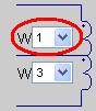
The winding order can be changed by the list box. W1 means the most inner layer.
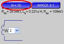
The number of turns for each winding is shown in the blue button. You can press this button to modify the number of turns.
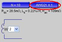
The wire information for each winding is shown in the blue button. It shows the Wire name and the number of parallel wires. You can press this button to modify it.

The “Total Loss” means the overall losses of the power supply and is shown at the top of the interface and will be automatically updated for any changed in transformer design.

The “Transformer Loss” means the losses of the whole transformer and is shown at the top of the interface and will be automatically updated for any changed in transformer design.

The “Bm” means the peak flux density of the transformer and is shown at the top of the interface and will be automatically updated for any changed in transformer design.

You can clone the current transformer and produce a set of transformer and place them in parallel or in series.
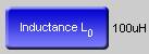
Inductance value is shown in the interface. On the left there is a blue button which can be used to modify the inductance.
Information on the selected core and selected magnetic materials is shown. You can press the blue button to change it.
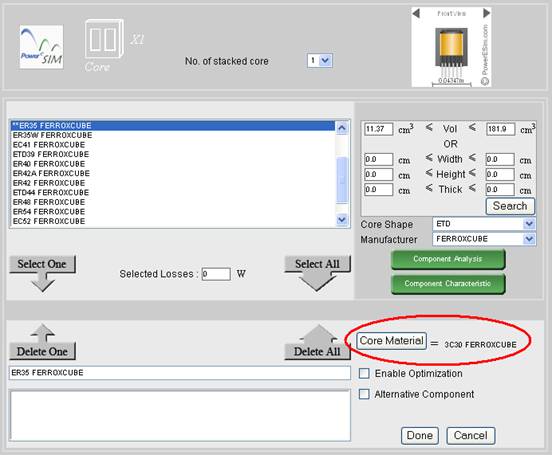
After you press on “Core Shape”, you can see the following page.
You can click on “Core Material” button on the bottom right to select different core material.
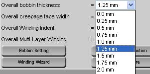
Overall bobbin thickness is a short cut to change all the left, upper and lower bobbin thickness at once.
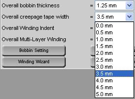
Overall creepage tape width is a short cut to change all the upper and lower creepage tape widths in all winding.
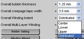
Overall Winding Indent is a short cut to change all the winding indents in all winding.
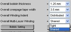
Overall Multi-Layer Winding is a short cut to change all the Multi-Layer Winding property.
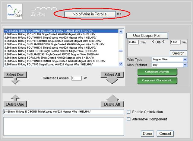
After you select the wire (section 7.8.12), you can see the above page.
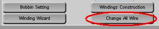
There is a shortcut button “Change All wire” that can change the wire for all winding by one step only.
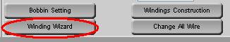
After you press the button “Winding Wizard”, you can see the following page and set the winding wizard option.
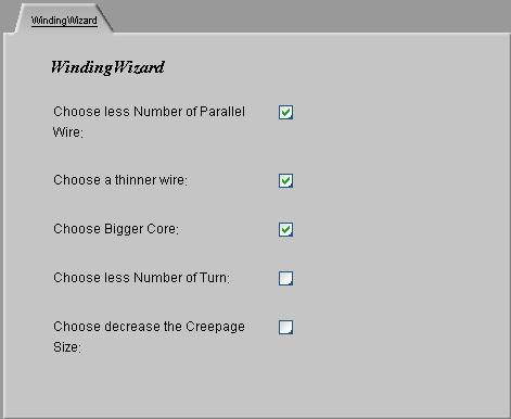
The check box in the “Winding Wizard” page provide a list of allowable background actions when the wire winding area is bigger than the allowable winding window area.

After press the button “Bobbin Setting”, then you can see
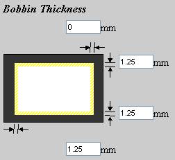
All four side of the bobbin can be individually adjusted.

After press the button “Bobbin Setting”, then you can see

After press the button “Bobbin Setting”, then you can see
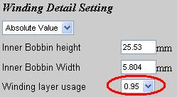
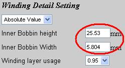
The winding layer usage is the usage ratio between the allowable bobbin height and Inner Bobbin height.

After press the button “Bobbin Setting”, then you can see
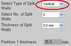
User can choose Vertical or Horizontal type of split wall.
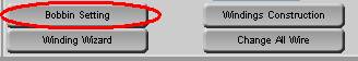
After press the button “Bobbin Setting”, then you can see
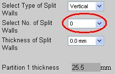
User can design number of split walls by choosing from “Select No. of Split Walls”

After press the button “Bobbin Setting”, then you can see
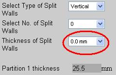
User can design the thickness of the split wall by choosing from “Thickness of Split Walls”
If you set more than 1 split walls in section "Configure number of split walls", you can see
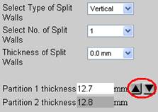
User can design the individual window height of each partition by clicking the arrows to increase or decrease partition thickness.
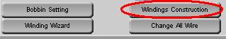
After pressing the button “Winding Construction”, user will see the “Advance Winding Construction” page
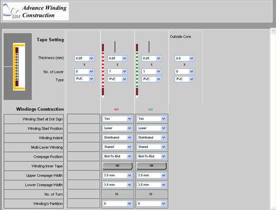
Basically each copper winding has its inherent tape winding for insulation. If no insulation is need set No. of layer to 0.
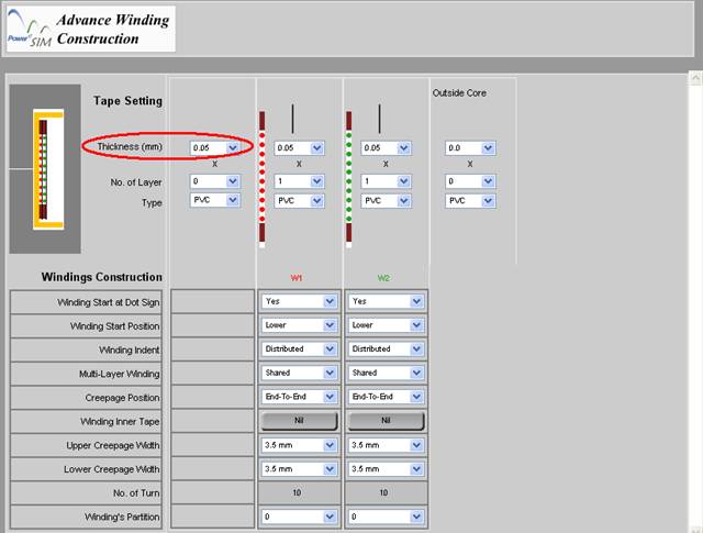
The thickness of tape can be set by changing the value of “Thickness (mm)”
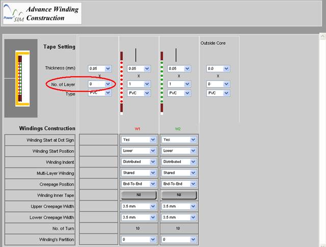
The no of turn of the tape can be set by changing the value of “No. of Layer”
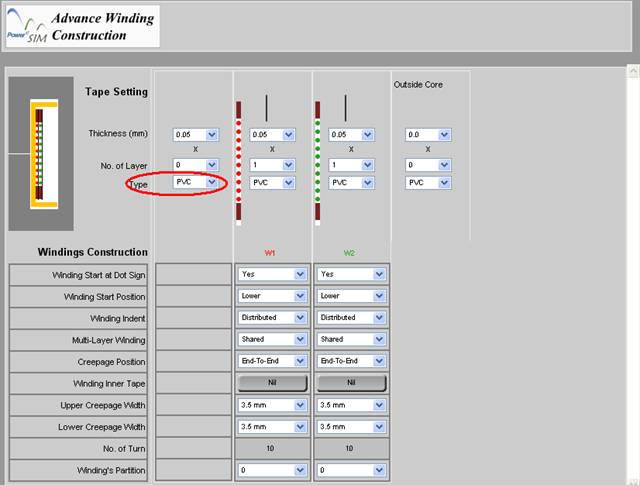
The material of the tape can also be set by “Type”
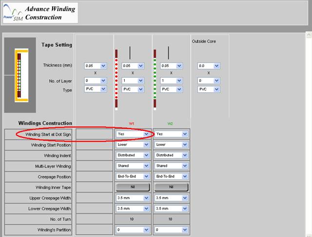
User can choose whether the dot sign is lie with winding started at the “Winding Start at Dot Sign” box.
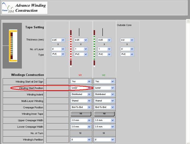
User can choose the winding start position at the “Winding Start Position” box.
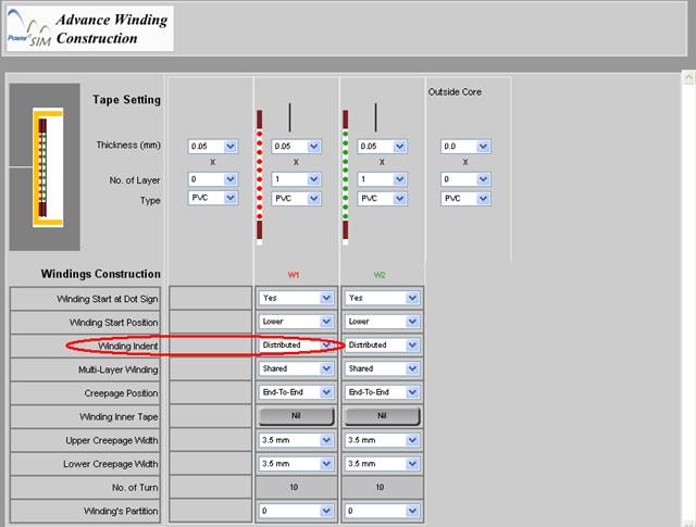
User can choose how the wire is packed at the “Winding Indent” box.
Distributed – wire will evenly wind in the allowable winding height.
Center – wire will be packed tight at center of the allowable winding height.
Low – wire will be packed tight at lower part of the allowable winding height.
Upper – wire will packed tight at the upper part of the allowable winding height.
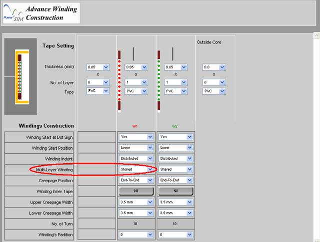
User can choose how the wire is arranged if more than 1 layer is needed to complete the winding in the “Multi-Layer Winding” box
Shared – wire will evenly shared in each layer
Tight – wire will be just tightly wind.
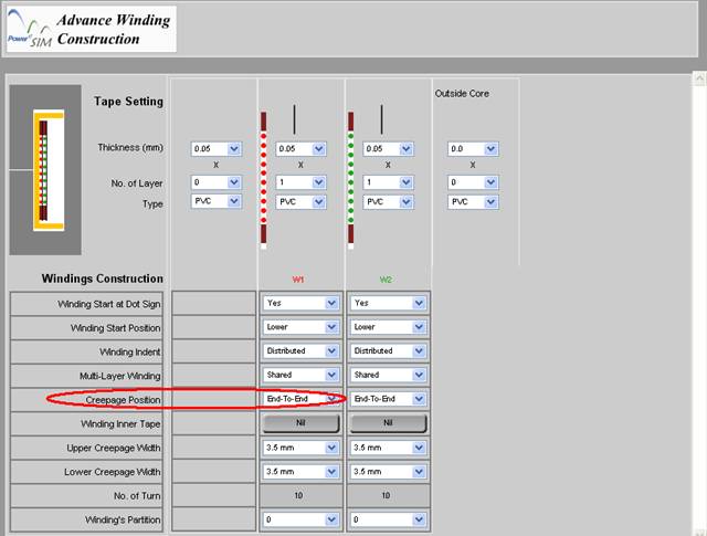
User can choose how the creepage tape is placed in the “Creepage Position” box
End-To-End – Creepage tape will placed at both end of the allowable winding height
Tight – Creepage tape will placed just beside the wire.
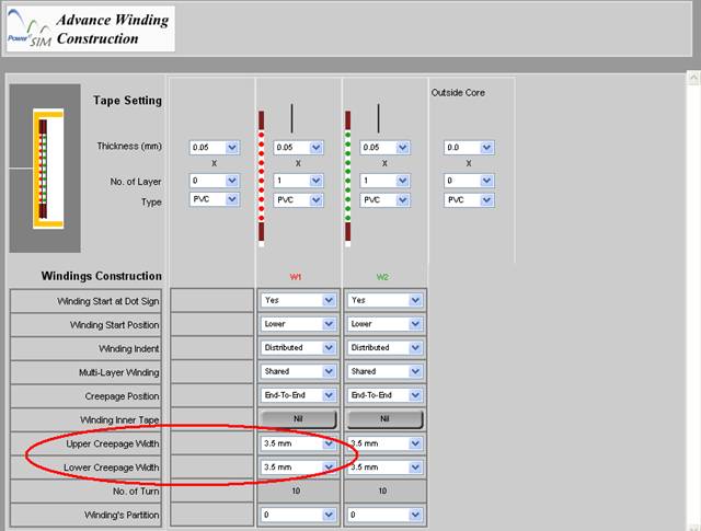
User can choose how the width of the creepage tapes by changing “Upper Creepage Width” or “Lower Creepage Width” box.
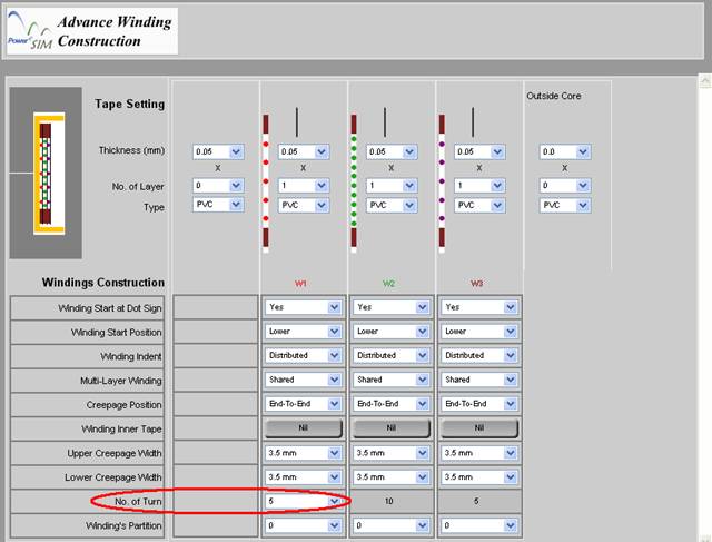
If more than 1 split sub-winding are made (section 7.8.9), you can change the number of turns of the each split winding by changing “No. of Turn” box.
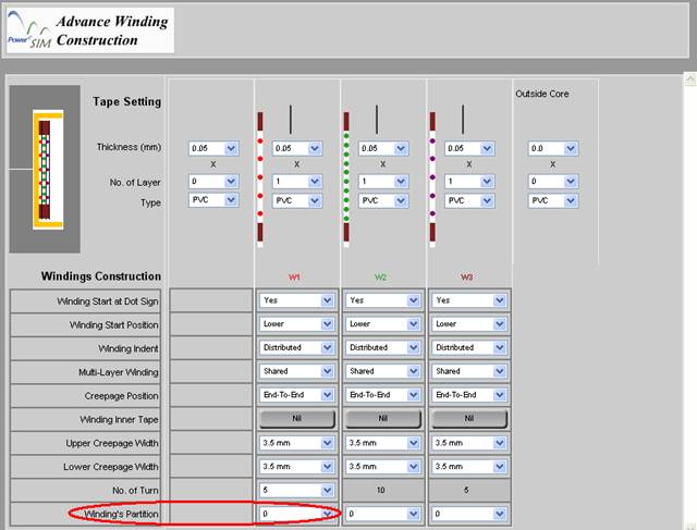
If more than one partition (section 7.8.31 & 7.8.32), user can locate the winding in any partition by changing “Winding’s Partition” box.
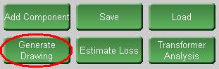
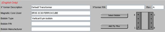
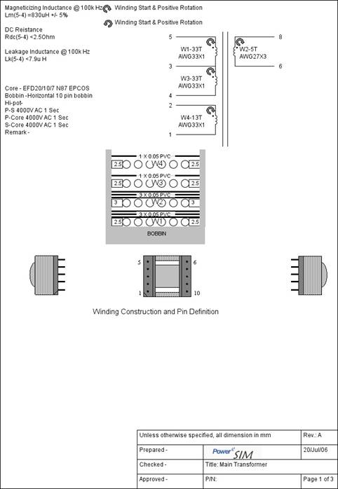
After pressing “Generate Drawing”, user can fill in all the detail information for making a professional transformer drawing.
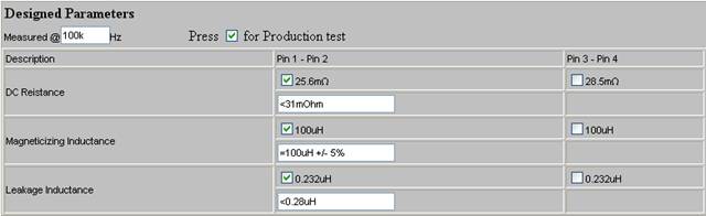
User can fill in checking parameter, e.g. DC resistance, Magnetizing Inductance and Leakage Inductance, for IQC. Once the check box is clicked, the value between the corresponding pins is enabled for inspection. Simulated value is recommended but user can change the actual IQC specification by change wording in the corresponding text box.
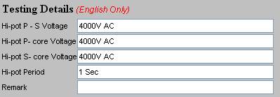
User can fill in the testing details in the bottom of Transformer Drawing interface.
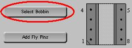
User press “Select Bobbin” at the top-right side and will see the following page.
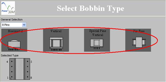
Click on the picture to select bobbin type
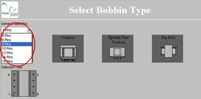
User can change the number of pins of bobbin there.
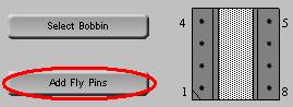
In “Generate Drawing” page (section 7.8.44), user press “Add Fly Pins” at the top-right side and user can see the following page.
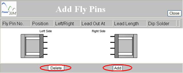
User can add or delete fly pins pressing corresponding button
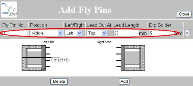
After adding fly pins (section 7.8.44.5), you can modify the detail of the fly pin or delete the corresponding fly pin by pressing “X”.
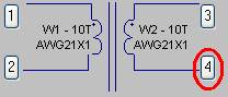
Press the number button can open an interface that can define the termination of a winding.
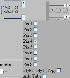
User can click one or more of the pins or fly pins available.
The 'Preview' button at the bottom can open a preview page of the transformer drawing.
| PowerEsim analysis tools |
| Copyright © 2026. PowerELab Limited. All rights reserved. |
