 |
|
|

Figure:General Transfer function
|
The Loop Analysis provides the interface to customize the transfer function and shows the open-loop gain and phase graphs.
 . . |
|
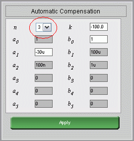
Figure:Input Interface
|
| Input ai and bi with using this interface. You can set the number of parameters by setting n. |
|
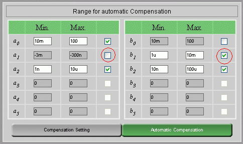
Figure:Range of parameters for Automatic compensation
|
| We provide the interface to find the parameters from the given ranges. This function is called "Automatic Compensation". You can tick the parameters you want to adjust for compensation or un-tick it to use the default value |
|
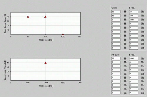
Figure:Compensation Setting
|
| Click on "Compensation Setting". You can set the expected Gain and Phase at different frequencies. Then, close this window and click on "Automatic Compensation" |
|
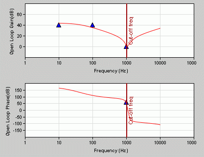
Figure:Gain and Phase after Automatic Compensation
|
| After Automatic Compensation, the gain and phase will response as the Compensation setting at different frequency. The adjust ai and bi are shown at the parameter setting interface. |
|

Figure:Transient Analysis
|
| Trigger Transient Analysis by clicking on this button. |
|
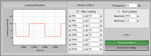
Figure:Transient Analysis Loading Setting
|
| In Transient Analysis, you can set the step loading current with this interface. Click on "Recalculate" to save the setting. |
|
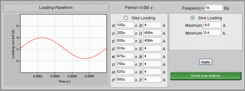
Figure:Transient Analysis Loading Setting
|
| Check the "sine loading" selection and set the upper and lower limit of sine loading. Click on "Recalculate" to save the setting. |
|
|
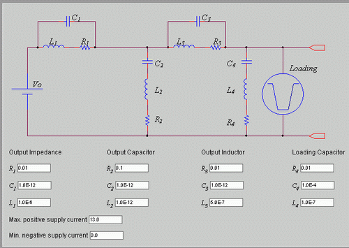
Figure:Advance User Setting
|
| Click on "Advance User Setting" at Loading Setting. You can set the Output Impedence, Output Capacitor, Output Inductor, Loading Capacitor, Max. positive current and Min negative current to customize the Transient Loading Response. |
|
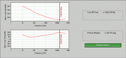
Figure:Loop Analysis
|
| After initializing the power supply design, the transfer function of the power supply is the product of the transfer functions of 3 modules: Converter (e.g. Flyback), Controller (PWM) and Compensation (Feedback). |
|
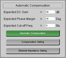
Figure:Automatic Compensation
|
You can set the expected Gain Margin, Phase Margin and Cross-over Frequency calculated by Automatic Compensation.Similar to the standalone Loop Analysis, you can set the expected gain and phase at different frequencies. Or you can use the default setting  by the expected value set before. Click on the "Automatic Compensation" by the expected value set before. Click on the "Automatic Compensation" |
|
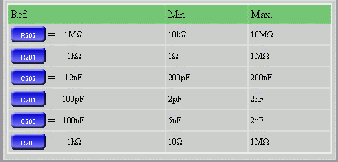
Figure:Automatic Compensation of circuit
|
| The transfer function is set by 3 modules. During the Automatic Compensation, some of resistors and capacitors in the 3 circuits are changed so to adjust the gain and phase value at different frequency. Different circuits may have different set of resistors and capacitors as the variant. |
|
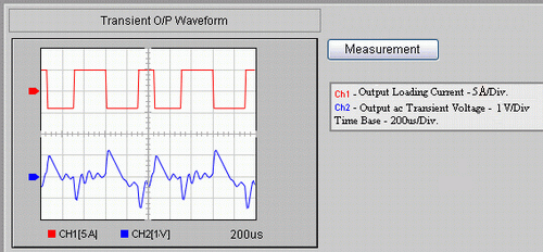
| The transient analysis is based on the transfer function from 3 modules to simulate the transient response during the operation of power supply. |
|

Figure:Select output
|
| You can select the output that you would like to monitor the transient response. |
|
| |


.


