PowerEsim Manual - Getting Start PowerEsim is a free web-based software providing power supply (SMPS) design, transformer design, magnetic design, loss analysis, thermal analysis, waveform analysis, MTBF analysis, BOM building, DVT analysis and optimization of power supply (SMPS).Click to try PowerEsim (www.powerEsim.com)
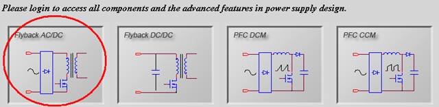
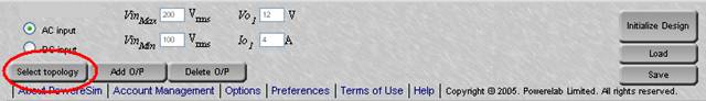
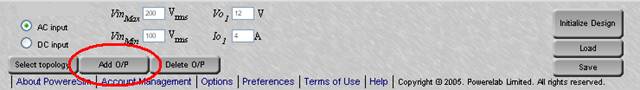
Select topology at front page Select topology at other sub-page Add more outputs Changing input voltage and current First thing to do - Initialize Design Add Stack Winding Select a part from schematic page Component Selection User Interface - searched components box Change a component from database Preview Component shape Analysis Particular Component View Component Characteristics Select PWM Controller Block Change PWM Controller Circuit Select Feedback Block Change Feedback Circuit Recalculate charts on the front page. Print Schematic Diagram
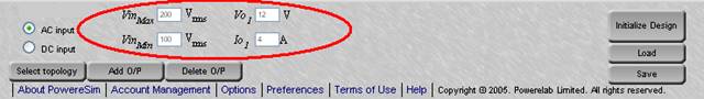
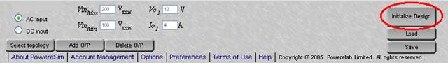
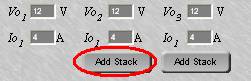
VinMin - VinMax , output voltage Vo and rated current Io at each output.
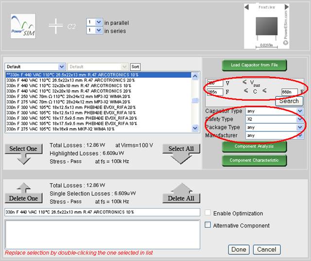
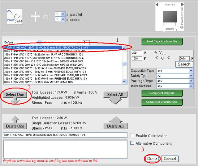
Fill in the range of the searching criteria, and press “Search,” all the component fulfill the criteria will be displayed at the searched components box and ready to be chosen.
Total Losses will be shown for the converter using the highlighted component.
Highlighted Losses will be shown for the highlighted component.
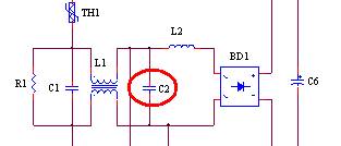
Select any one component from the searched components box
Click “Select One”
Total Losses will be shown for the converter using the selected component.
Selected Losses will be shown for the selected component.
Press “Done” after selection
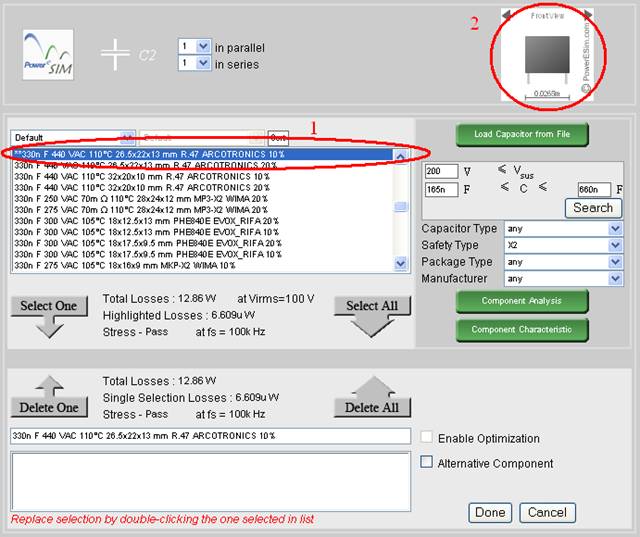
Highlight any one component from the list
The component’s shape is shown at upper right corner
Highlight any one component from the list
Press “Component Analysis”
A component analysis page will be displayed.
If highlighted component is changed, press “Component Analysis” again to refresh.
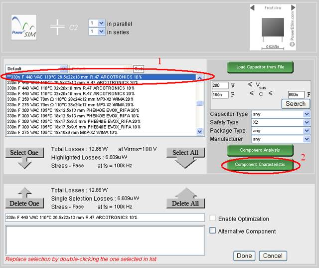
Highlight any one component from the list
Press “Component Characteristic”
A component characteristic page will be displayed.
If highlighted component is changed, press “Component Characteristic” again to refresh.
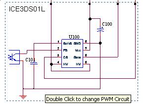
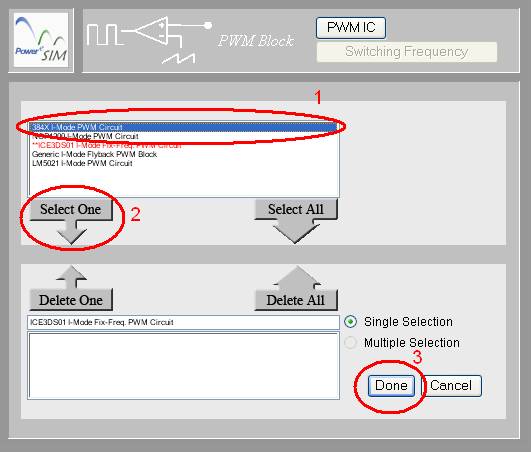
Highlight any one circuit from the list
Press "Select One"
Press “Done” after selection
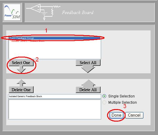
Highlight any one circuit from the list
Press “Select One”
Press “Done” after selection
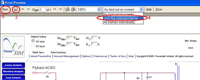
To print the circuit diagram, there are several steps.
Use mouse and click on the circuit diagram ONCE.
If you are using Internet Explorer, choose File->Print Preview.
Click on "Page Setup"
Choose "Only the Selected Frame" from the top menu.
Finally click on “Print”
Copyright © 2024. PowerELab Limited. All rights reserved.