PowerEsim Manual - Loop Analysis |
|
| PowerEsim is a free web-based software providing power supply (SMPS) design, transformer design, magnetic design, loss analysis, thermal analysis, waveform analysis, MTBF analysis, BOM building, DVT analysis and optimization of power supply (SMPS). | |
| Click to try PowerEsim (www.powerEsim.com) | |
Loop analysis is a tool to let user arbitrary draw a transfer function by vary the coefficient or component from the feedback block. On the other way, curve fitting can be done by entering points of expected gain or expected phase, by pressing "Automatic Compensation" button, the coefficient of the transfer function or components will be changed to fit those points.
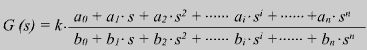
The Loop Analysis provides the interface to customize the transfer function and shows the gain and phase of the transfer function G(s)
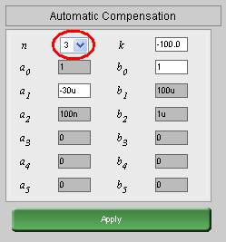
Input ai and bi with using this interface. You can set the number of parameters by setting n., where n is the order of the transfer function.
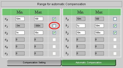
The range of ai and bi should be specified for curve fitting purpose. For coefficient which user may not want to be changed by our non-linear regression curve fitting engine, user simply unchecks the check box as shown above.
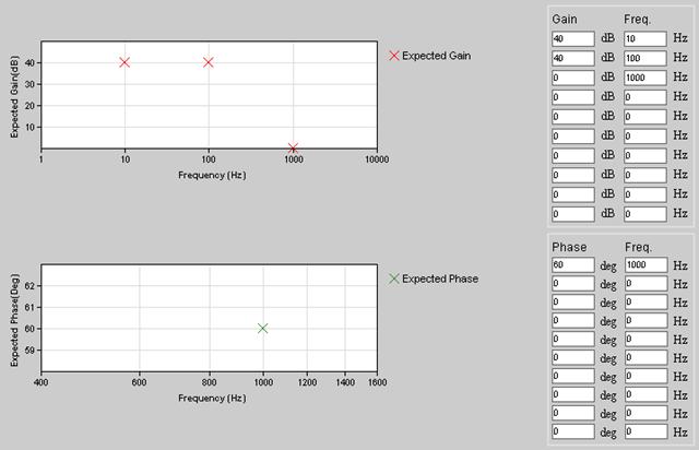
Click on "Compensation Setting". You can set the expected Gain and Phase at different frequencies. Then, close this window and click on "Automatic Compensation"
After Automatic Compensation, a non-linear regression curve fitting will change ai and bi value so as to fit the expected gain and expect phase as close as possible. The adjusted ai and bi are shown at the parameter setting interface.
How well the transfer function fit all those points depends on the number of ai and bi allowed to change and the range of ai or bi
![]()
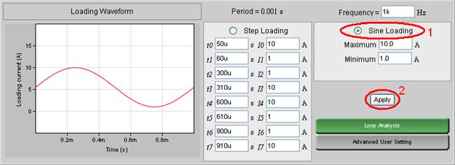
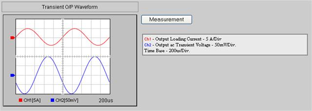
Non-linear load transient analysis can be done by pressing "Transient Analysis." The voltage waveform will be displayed according to the loading current shape and output impedance defined by user.
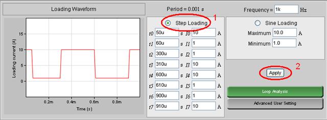
In Transient Analysis
Once apply is clicked. AC voltage change and the response also can be seen on the setting at "Advance User Setting"
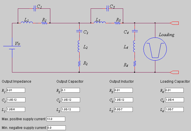
After Click on "Advance User Setting" at Loading Setting, You can set the output impedance of a generic power supply by setting "Output Capacitor", "Output Inductor", "Loading Capacitor", "Max. positive supply current" and "Min. negative supply current" to customize the generic power supply characteristic.
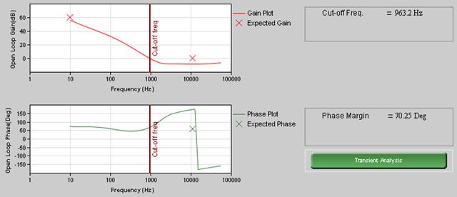
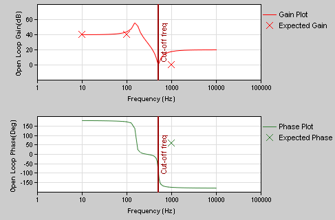
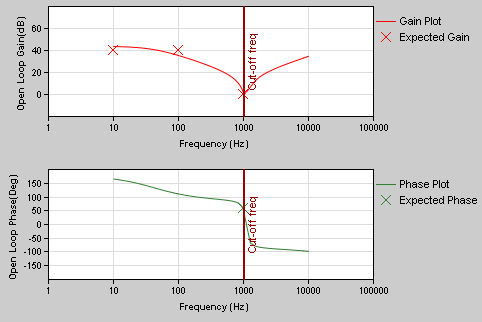
After initializing a power supply design, the loop analyzer will take the open loop transfer function of the power supply user chosen. Current injection method is employed for small signal analysis, all the detail parasitic element, e.g. ESR, ESL, ESR vs Temp. and high frequency effect, are already considered. User no longer needs to do the tedious analysis.
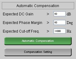
User can set the Expected Gain Margin, Expected Phase Margin and Expected Cut-off Frequency of the power supply and press "Automatic Compensation" for the machine to find proper component to fit those points.
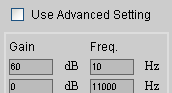
Or user can go into the "Compensation Setting," click the check box "Use Advanced Setting" and enter point by point of the expected gain and expected phase. Go back and click on the "Automatic Compensation" our machine will try to provide the corresponding feedback component which will best fit user defined points.
For example, if you choose the Generic Feedback circuit, the parts in the circuit are modeled as values such as capacitance or resistance. You can change particular values from the generic component page.
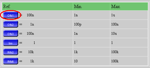
Click on the component button and then you can see the following page. Uncheck the checkbox if you don't want the component used for automatic compensation.
Not every component are allowed for automatic compensation, only the component with a check box "Enable for Automatic Loop Compensation" at the upper right corner of component selection user interface.
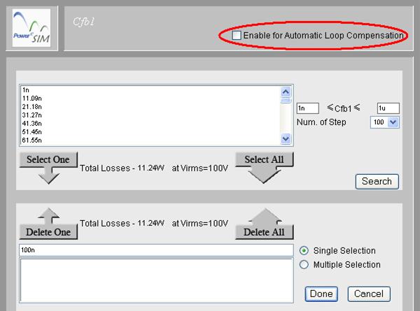
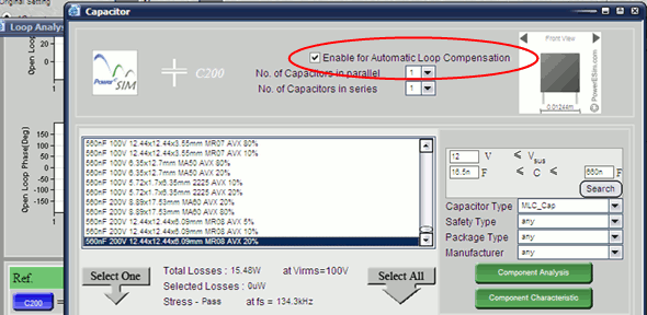
The range of the component used for automatic loop compensation is all component listed in the searched components box which is defined by the searching criteria.
The transient analysis is based on the small signal close loop transfer function to derive equivalent output impedance. Non-linear effect caused by the limitation of sink and source current have also considered.
![]()
You can select the output that you would like to monitor the transient response.
| PowerEsim analysis tools |
| Copyright © 2026. PowerELab Limited. All rights reserved. |
