 | PowerEsim Help Manual |
PowerEsim is a free web-based software providing power supply (SMPS) design, transformer design, magnetic design, loss analysis, thermal analysis, waveform analysis, MTBF analysis, BOM building, DVT analysis and optimization of power supply (SMPS).
|
Click to try PowerEsim (www.powerEsim.com)
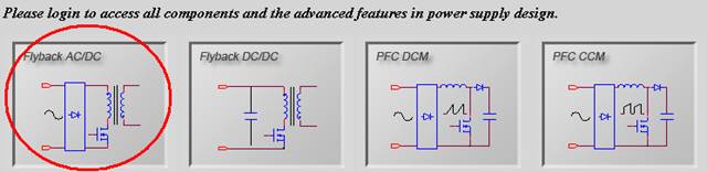
Click on
any topology window to select a topology
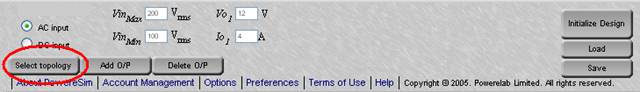
You can
click “Select topology” to go back to front page to select another topology
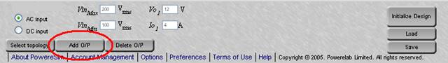
Click
the link “Add O/P” to add more output.
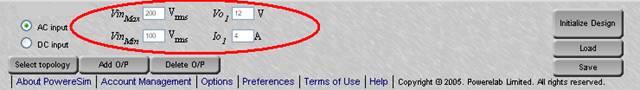
Enter
the input voltage range VinMin
- VinMax, output voltage Vo
and rated current Io at each output.
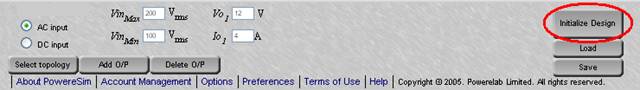
Once
input and output are defined, press the button “Initialize Design.” A
preliminary design will be recommended by PowerEsim.
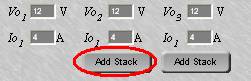
You can
press “Add Stack” to add ac stack winding before
and after the design initialized.
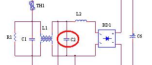
After design
initialized, you can click on the component to go into the component selection
user interface.
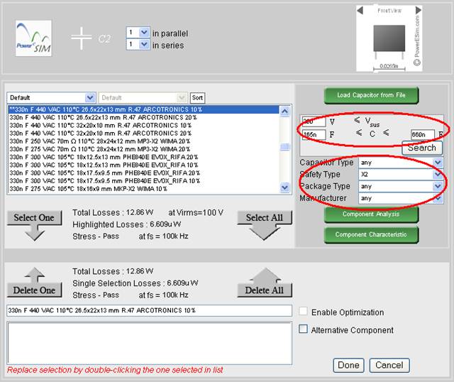
- Fill in the range of the searching
criteria, and press “Search,” all the component fulfill the criteria will
be displayed at the searched components box and ready to be chosen.
- “Total Losses” will be shown
for the converter using the highlighted component.
- “Highlighted Losses” will be
shown for the highlighted component.
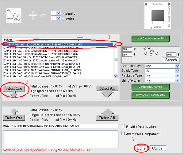
- Select any one component
from the searched components box
- Click “Select One”
- “Total Losses” will be shown
for the converter using the selected component.
- “Selected Losses” will be shown for the selected component.
- Press “Done” after selection
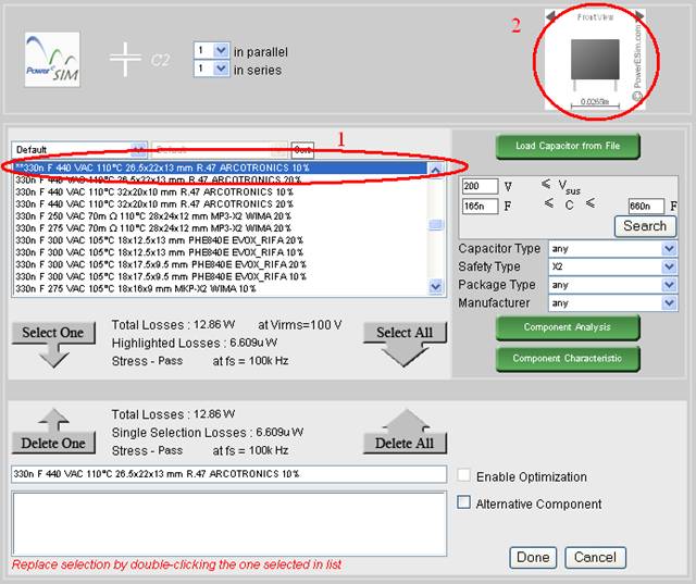
- Highlight any one component
from the list
- The component’s shape is
shown at upper right corner

- Highlight any one component
from the list
- Press “Component Analysis”
- A component analysis page
will be displayed.
- If highlighted component is
changed, press “Component Analysis” again to refresh.
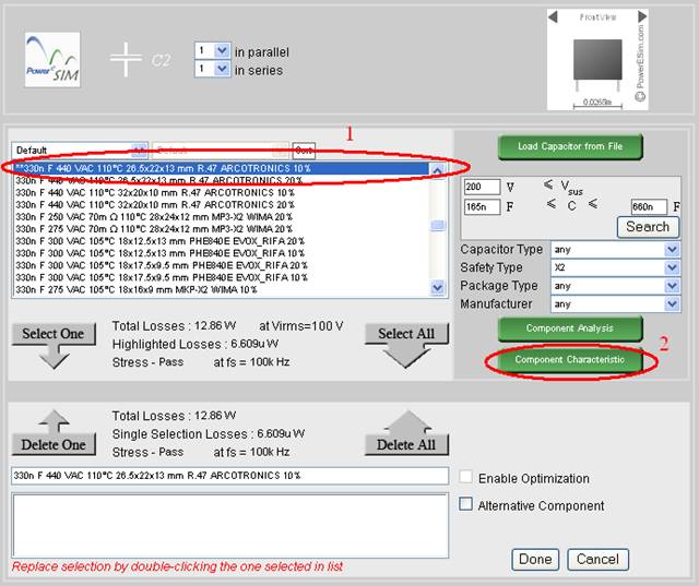
- Highlight any one component
from the list
- Press “Component Characteristic”
- A component characteristic
page will be displayed.
- If highlighted component is
changed, press “Component Characteristic” again to refresh.
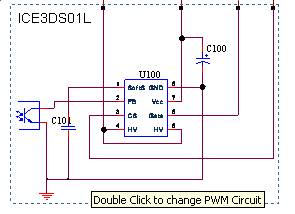
Double
click the block in order to view the current PWM block
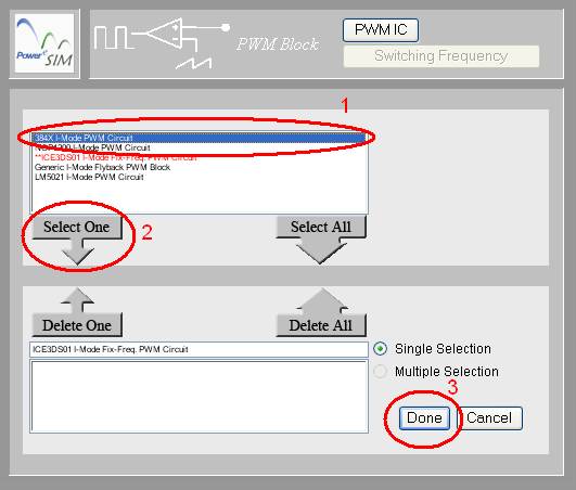
- Highlight any one circuit
from the list
- Press “Select One”
- Press “Done” after selection
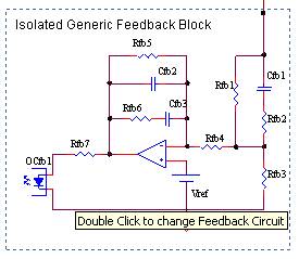
Double
click the block in order to view the current Feedback block
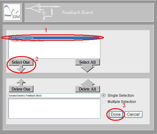
- Highlight any one circuit
from the list
- Press “Select One”
- Press “Done” after selection
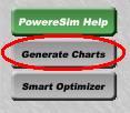
Press “Generate
Charts” button
To print the circuit diagram, there are
several steps.
- Use mouse
and click on the circuit diagram ONCE.
- If you
are using Internet Explorer, choose File->Print
Preview.
- Click on
"Page Setup"
 and choose Orientation to be Landscape.
- Choose
"Only the Selected Frame" from the top menu.
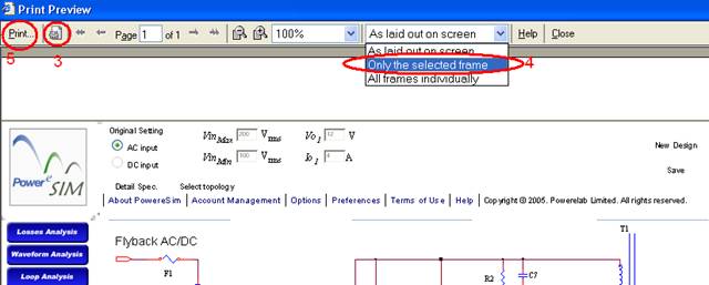
- Finally click on “Print”
Click to try PowerEsim (www.powerEsim.com)
 Prev.: PowerEsim Account Management