Magetic Builder (Magnetic Design Sofrtware) of PowerEsim Help Manuals |
|
| PowerEsim is a free web-based software providing power supply (SMPS) design, transformer design, magnetic design, loss analysis, thermal analysis, waveform analysis, MTBF analysis, BOM building, DVT analysis and optimization of power supply (SMPS). | |
| Click to try PowerEsim (www.powerEsim.com) | |
13 Magnetic Builder
13.1 What is magnetic builder?
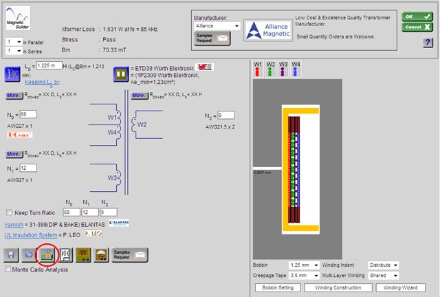
Magnetic Builder is a useful magnetic design software. It is a tool for user to create his/her own magnetic component by selecting different ferrite core, bobbin type and winding method. Engineering drawing will be automatically produced to reduce user work load.
All the transformer build can be saved and reused onto a power supply, as long as the winding number are matched.
13.2 Create a new transformer
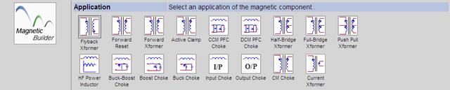
Click “Magnetic Builder”, select the application of the
magnetic component
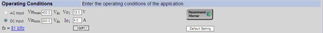
Input
the Operating conditions of the application and click “Recommend Xformer”
l You may select AC/DC input by
clicking on the radio box at the left of the words “AC Input” and “DC Input”
l Operating frequency can be changed by clicking the frequency value. High frequency transformer is also available as PowerEsim will suggest a suitable transformer for the requested operating frequency.
l Vinmax and Vinmin
can be changed by updating the value in the text box
l Number of output can be changed
by clicking the + and – button at the right/left hand side of “O/P”. Maximum
number of output are restricted between 1 to 5 according to the application
selected
l Output voltage and current can be
self-defined by updating the value of the corresponding text boxes
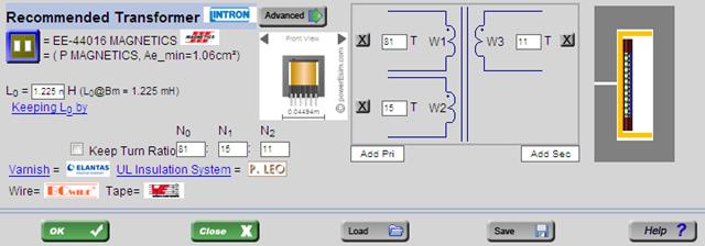
l You may change the Core shape,
material and manufacturer by clicking the ![]() button.
button.
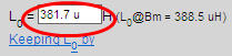
l Change Lo by input new value to
the textbox at the right of L0 =
l “Keeping L0 by” allows users
select how to maintain L0 of the transformer
l When the checkbox at the left of
Keep Turn Ratio is clicked, once you change the number of turns in the
transformer illustration in the middle (the figure above “Add Pri” and “Add Sec”)
other windings will update the number of turns in ratio
l Click the word “Vanish” to change
the type and manufacturer of vanish used
l Click the word “UL Insulation
System” to change the manufacturer
l Click “Add Pri” button to
increase the number of primary winding
l Click “Add Sec” button to
increase the number of secondary winding
l Click ![]() at the side of the windings to delete that
winding
at the side of the windings to delete that
winding
l Update value of the textbox in
the winding to change the number of turns of that winding
l Click ![]() to put the transformer in BOM, or
to put the transformer in BOM, or
l Click ![]() to save the transformer file to your computer,
or
to save the transformer file to your computer,
or
l Click ![]() to open “Magnetic Builder - Winding
Construction” page for further implementation to the transformer.
to open “Magnetic Builder - Winding
Construction” page for further implementation to the transformer.
13.3 Magnetic Builder – Winding
Construction
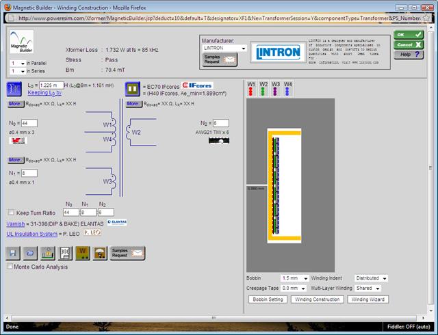
Advanced settings on the transformer can be
control in “Magnetic Builder - Winding Construction” page
13.4
Add number of primary winding
1.
Click ![]() button to open Winding Detail Page
button to open Winding Detail Page
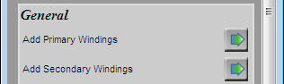
2.
Click ![]() at the right of “Add
Primary Windings” under
section “General”
at the right of “Add
Primary Windings” under
section “General”
13.5 Add number of secondary winding
1.
Click ![]() button to open Winding Detail Page
button to open Winding Detail Page
2.
Click ![]() at the right of “Add Secondary Windings” under section “General”
at the right of “Add Secondary Windings” under section “General”
13.6
Add Bifilar
Click ![]() button to open Winding Detail Page
button to open Winding Detail Page
Click on
the arrow at the right of the winding you would like to add bifilar
![]()
Winding
with the same number of turn will be shown and can be selected for bifilar.
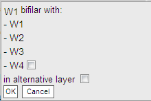
You may
select the windings are bifilar in same layer or in alternative layer
13.7 Flux Band
Click ![]() button to open Winding Detail Page
button to open Winding Detail Page
![]()
Click
the arrow button at the right of “Flux Band Setting”
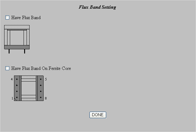
Two type
of flux band are supported. Click the checkbox to add the flux band.

After
clicked the checkbox, the core with the flux band can be preview. The Flux band
thickness and width can be set.
13.8 Add Primary / Secondary Winding

Extra
Winding can be added by clicking “Add Pri Wdg” or “Add Sec Wdg.” The usage of this feature is
recommended for non-operating winding only. User is recommended to preset the
proper winding number at the “Number of Windings” page.
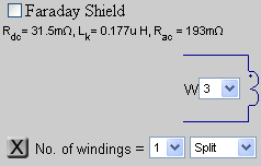
13.9 Faraday Shield
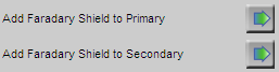
The user
can add a Faraday Shield by clicking the respective ![]() button
button
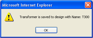
13.10 Add a transformer to the design
After creating a new transformer, you can
add it to the design by pressing “Add Component”.
When the transformer is added, the message with transformer's designator is
shown.
13.11 Make split winding or parallel winding
Click ![]() button to open Winding Detail Page
button to open Winding Detail Page
![]()
User can “Split” a winding to several section by choosing from “No. of windings” or Parallel Winding in any winding for sandwiching winding method.
13.12 Customize the winding order
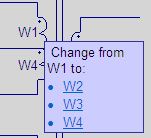
Move the
mouse on the winding that you would change the winding order. W1 means the most inner layer.
13.13 Adjust number of turns for each winding
![]()
The number of turns for each winding is
shown in the input
column. You can modify the number of turns and the number of turns will
update immediately.
13.14 Select the wire used for each winding

The wire information for each winding is
shown in the text
below number of turns. It shows the Wire name and the number
of parallel wires. You can press the text to modify it.
13.15 Every change can affect the total loss
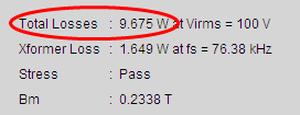
The “Total Loss” means
the overall losses of the power supply and is shown at the top of the interface
and will be automatically updated for any changed in transformer design.
13.16 Every change can affect transformer loss
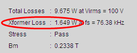
The “Transformer Loss” means the losses of the whole transformer and is shown at the top of the interface and will be automatically updated for any changed in transformer design.
13.17 Some change can affect the Peak
Flux
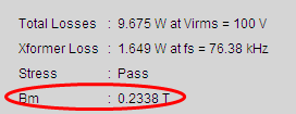
The “Bm” means
the peak flux density of the transformer and is shown at the top of the
interface and will be automatically updated for any changed in transformer
design.
13.18 Putting transformers in parallel / series
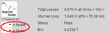
You can clone the current transformer and
produce a set of transformer and place them in parallel or in series.
13.19 Changing the transformer inductance
Inductance value is shown in the interface.
On the left there is a text box which can be used to modify the
inductance.
13.20 Select different core shape and manufacturer
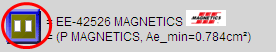
Information on the selected core and
selected magnetic materials is shown. You can press the blue button to change
it.
13.21 Select different core material
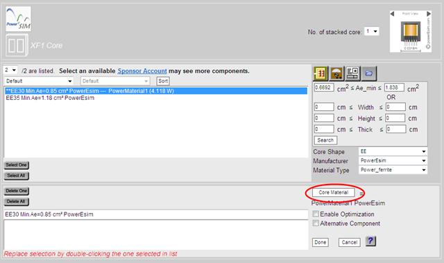
After
you press on “Core Shape”, you can see the following page.
You can
click on “Core Material” button on the bottom right to
select different core material.
13.22 Overall bobbin thickness can be adjusted
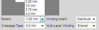
Overall bobbin thickness is a short cut to
change all the left, upper and lower bobbin thickness at once.
13.23 Adjust the overall creepage tape width
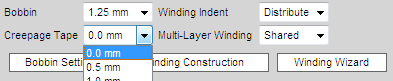
Overall
creepage tape width is a short cut to change all the
upper and lower creepage tape widths in all winding.
13.24 Adjust the Overall winding indent
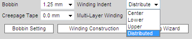
Overall
Winding Indent is a short cut to change all the winding
indents in all winding.
13.25 Adjust the Overall Multi-Layer Winding setting
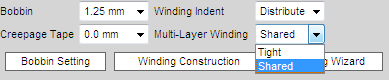
Overall
Multi-Layer Winding is a short cut to change all the
Multi-Layer Winding property.
13.26 Change the
No. of wire in parallel
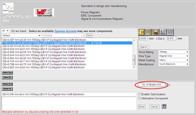
After
you select the wire (section 13.14), you can see the above page.
13.27 Adjust the overall wire used in all winding
Click ![]() button to open Winding Detail Page
button to open Winding Detail Page
![]()
There is a shortcut button “Change All wire” that
can change the wire for all winding by one step only.
13.28 How to change the Winding Wizard option?
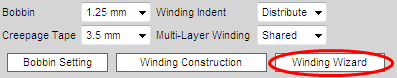
After
you press the button “Winding Wizard”, you can see the following page
and set the winding wizard option.
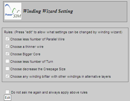
Press
Edit Button to change setting
The
check box in the “Winding Wizard” page provide a list of allowable background actions when the wire
winding area is bigger than the allowable winding window area.
13.29 Change bobbin thickness on each side
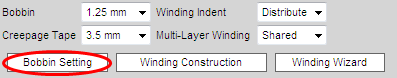
After
press the button “Bobbin Setting”, then you can see
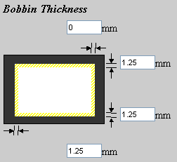
All four
side of the bobbin can be individually adjusted.
13.30 Configure the bobbin winding window dimension
After
press the button “Bobbin Setting”, then you can see
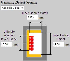
13.31 How to change the winding layer usage?
After
press the button “Bobbin Setting”, then you can see
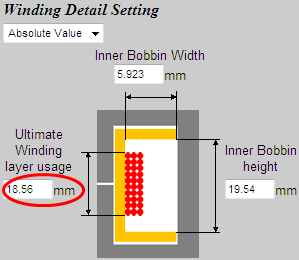
The
winding layer usage is the maximum allowable bobbin height.
13.32 Bobbin with split walls
After
press the button “Bobbin Setting”, then you can see
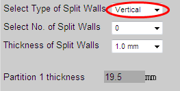
User can
choose Vertical or Horizontal type of split wall.
13.33 Configure number of split walls
After
press the button “Bobbin Setting”, then you can see
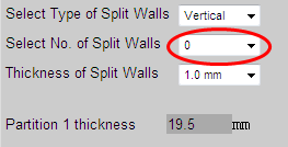
User can
design number of split walls by choosing from “Select No. of Split Walls”
13.34 Configure the thickness of split walls
After
press the button “Bobbin Setting”, then you can see
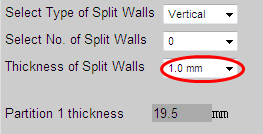
User can
design the thickness of the split wall by choosing from “Thickness of Split
Walls”
13.35 Configure the thickness of each partition
If you
set more than 1 split walls in section 7.8.31, you can see
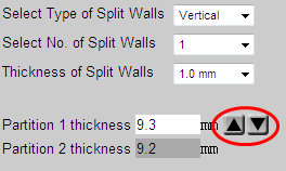
User can
design the individual window height of each partition by clicking the arrows to
increase or decrease partition thickness.
13.36 Configure tape characteristic in each winding
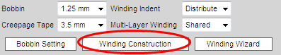
After
pressing the button “Winding Construction”, user will see the “Advance
Winding Construction” page
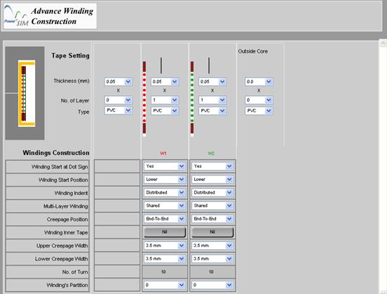
Basically each copper winding has its inherent tape winding for insulation. If no insulation is need set No. of layer to 0.
13.36.1
Configure the tape thickness of each winding
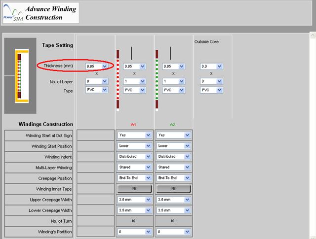
The
thickness of tape can be set by changing the value of “Thickness (mm)”
13.36.2
Configure the number of layer
in each winding
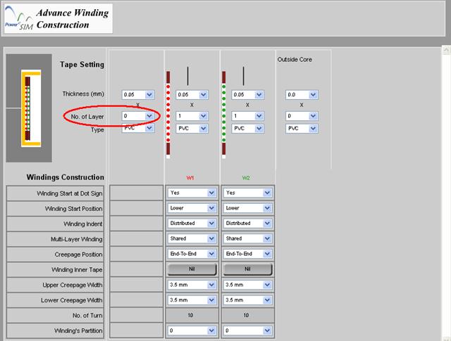
The no
of turn of the tape can be set by changing the value of “No. of Layer”
13.37 Configure the tape type used in each winding
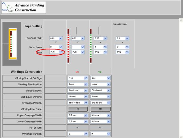
The
material of the tape can also be set by “Type”
13.38 Configure the dot sign of each winding
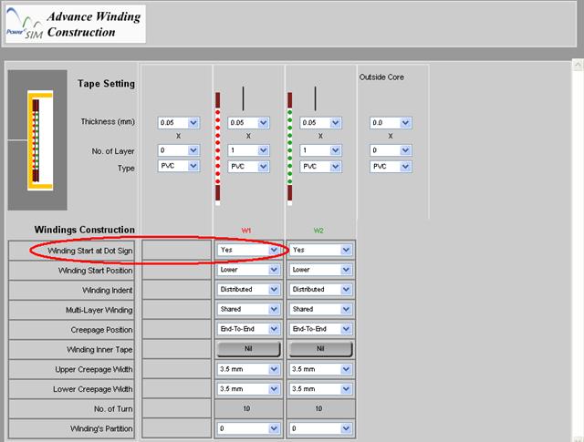
User can
choose whether the dot sign is lie with winding started at the “Winding Start
at Dot Sign” box.
13.39 Define the winding start position of each winding

User can
choose the winding start position at the “Winding Start Position” box.
13.40 Configure the winding indent of each winding
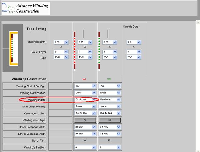
User can
choose how the wire is packed at the “Winding Indent” box.
Distributed – wire will evenly wind in the allowable winding height.
Center – wire will be packed tight at center of the allowable winding
height.
Low – wire will be packed tight at lower part of the allowable winding
height.
Upper – wire will packed tight at the upper part of the allowable
winding height.
13.41 Configure the characteristic of multi-layer winding of each winding
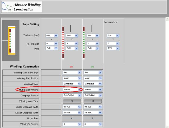
User can
choose how the wire is arranged if more than 1 layer is needed to complete the
winding in the “Multi-Layer Winding” box
Shared – wire will evenly shared in each layer
Tight – wire will be just tightly wind.
13.42 Creepage position
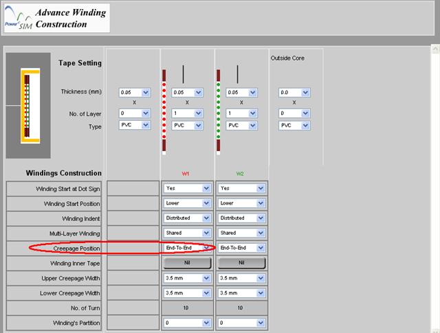
User can
choose how the creepage tape is placed in the “Creepage Position” box
End-To-End – Creepage tape will
placed at both end of the allowable winding height
Tight – Creepage tape will placed just beside the wire.
13.43 Creepage
width of each winding

User can
choose how the width of the creepage tapes by changing “Upper Creepage Width” or “Lower Creepage Width” box.
13.44 Change the number of turns of each split winding
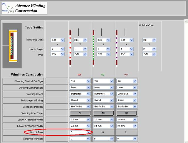
If more
than 1 split sub-winding are made (section 7.8.9), you can change the number of turns of the each split
winding by changing “No. of Turn” box.
13.45 Locate the winding in which bobbin partition
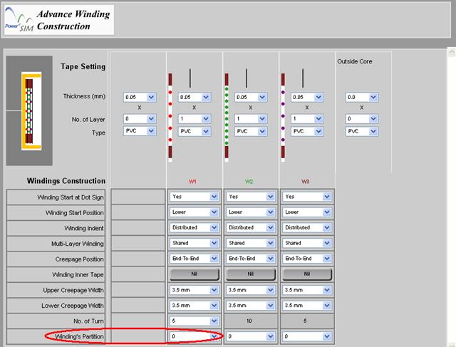
If more
than one partition (section 7.8.31 & 7.8.32), user can locate the winding in any partition by
changing “Winding’s Partition” box.
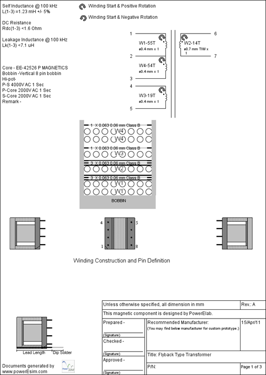
13.46 Generate Transformer Drawing
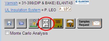
 After
pressing “Generate Drawing”, user can fill in all the
detail information for making a professional transformer drawing.
After
pressing “Generate Drawing”, user can fill in all the
detail information for making a professional transformer drawing.
13.46.1
Designed parameters of a
transformer
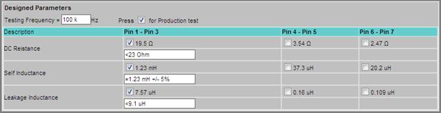
User can fill in checking
parameter, e.g. DC resistance, Magnetizing Inductance and Leakage Inductance,
for IQC. Once the check box is clicked, the value between the corresponding
pins is enabled for inspection. Simulated value is recommended but user can
change the actual IQC specification by change wording in the corresponding text
box.
13.46.2
Change the testing details of Transformer Drawing
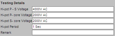
User can fill in the testing
details in the bottom of Transformer Drawing interface.
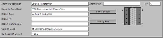
13.46.3
Different type of bobbin can be
selected
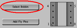
User press “Select Bobbin” at the top-right side and will
see the following page.
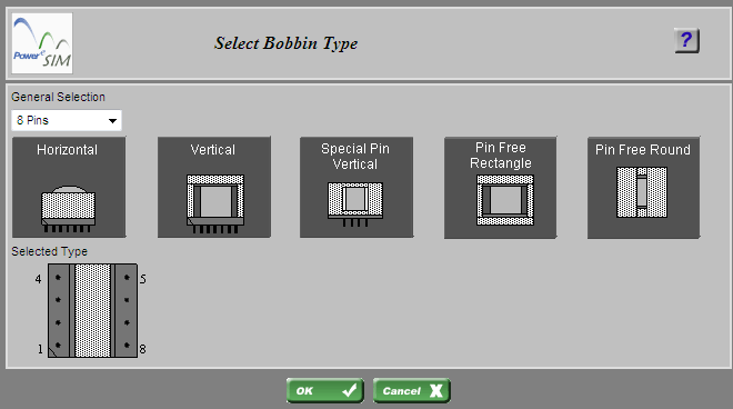
Click on
the picture to select bobbin type
13.46.4
Change the number of pins of
bobbin
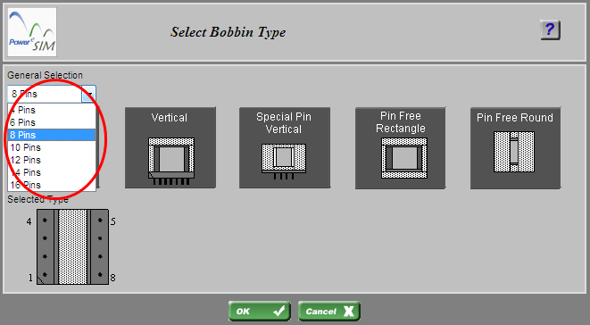
User can change the number of
pins of bobbin there.
13.46.5
Add/ delete fly pins
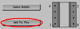
In “Generate
Drawing” page (section 7.8.44), user press “Add Fly Pins” at the top-right side and user
can see the following page.
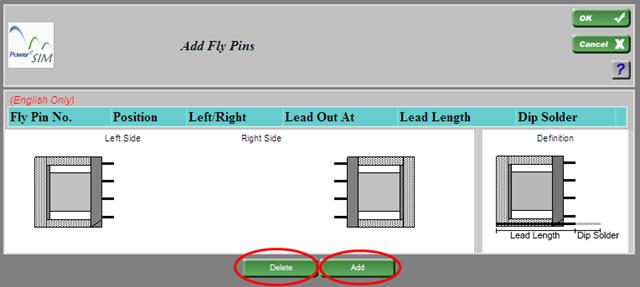
User can
add or delete fly pins pressing corresponding button
13.46.6
Configure details of fly pins
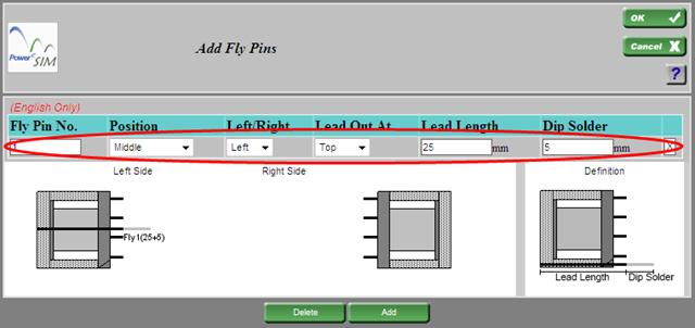
After
adding fly pins (section 7.8.44.5), you can modify the detail of the fly pin or delete
the corresponding fly pin by pressing “X”.
13.46.7
Define the termination pins of
a winding
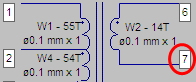
Press the number button can open an
interface that can define the termination of a winding.
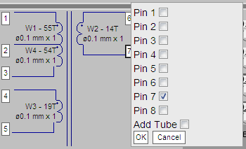
User can
click one or more of the pins or fly pins available.
13.46.8
Preview the Transformer drawing
page
The 'Preview' button at the bottom can open a preview page of the transformer drawing.
 Prev.: DVT Reports Prev.: DVT Reports | Next: Add Parts  |
Click to try PowerEsim (www.powerEsim.com)
|
Home | Download | Useful Link | Video Demo | About | Contact Us | Disclaimer | FAQ | Statistics Account Management | Options | Preferences | Help |
